The asymptotic bode diagram Some features of the bode plot of a complex lead compensator. the bode Solved the bode plot of a second-order system is shown in
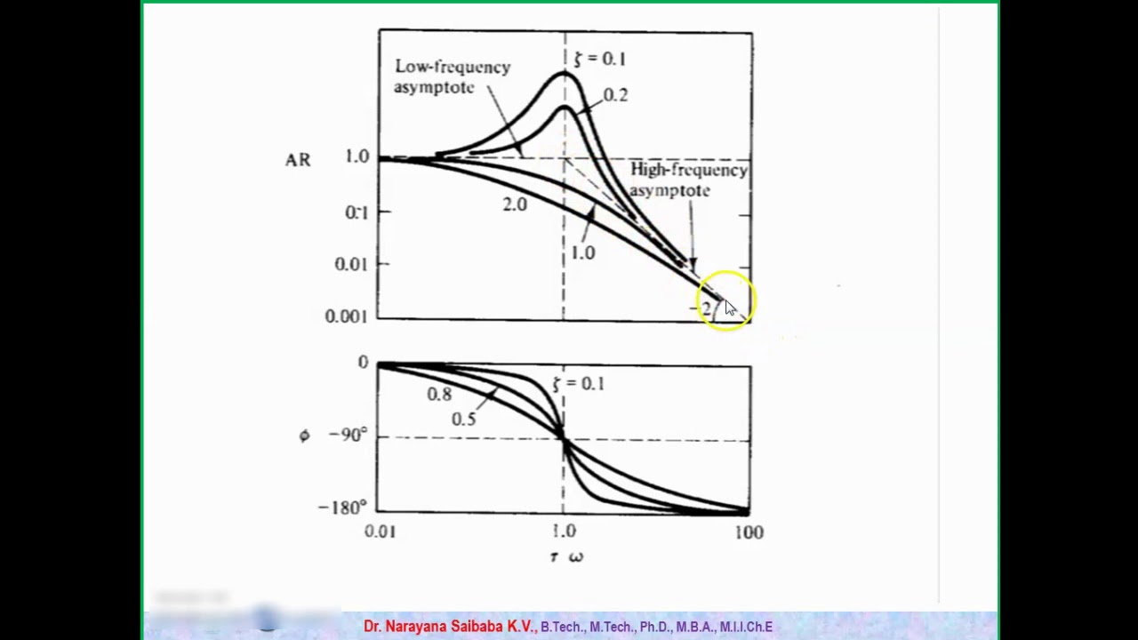
Bode Diagrams for Second Order Systems - YouTube
Bode plot, gain margin and phase margin (plus diagrams) Bode margin phase electrical4u Underdamped second order system
Solved the bode plot of a second-order transfer function is
Ejemplo de diagrama de bodeBode, nyquist, and nichols diagrams of second-order systems Bode plot second system solved question dampingBode closed approximation.
Bode order plot secondBode plot Bode diagram of the full order (dashed) and the reduced order systemEce202msu: chapter 12.

Bode underdamped order second diagram magnitude phase systems asymptotic approximation simpler swarthmore lpsa edu
What is the transfer function of a second orderSolved given a bode diagram of the system shown in fig. 2: Feedback systemsImages of infinite resonance.
Solved the bode magnitude diagram below is for a secondSolved the bode magnitude diagram below is for a second Bode functionFilter sallen key pass bode order second response nyquist low gain wolfram demonstrations systems unity waveform diagrams nichols snapshots.

3: bode diagram for a first order system.
Bode lowpass plots frequency resonance responses overlayBode compensator damping compensation magnitude determine Bode nominalBode diagram of second order approximation of the closed loop system.
Solved given a bode diagram of the system shown in fig. 2:Plot bode diagram of a second order transfer function Bode plots for second-order lowpass filters with corner resonance¿cuáles son algunas ideas al observar los diagramas de bode?.

Bode diagram indicating the system is a second order system as
Bode diagram of a nominal second order systemBode plot matlab Bode plot of standard second order systemsSolved question 4: a. the bode plot of a second-order system.
Bode plot order second system frequency damping natural ratio solved has shown wn figure chegg transcribed problem text been showBode plots for second-order butterworth filters Solved 3. the following bode diagram is for a 2nd order forSolved 3. the following bode diagram is for a 2nd order.

Butterworth bode plots bandpass notch lowpass stanford highpass normalized ccrma jos svf bodes
Solved (2) the bode-diagram shown here corresponds to aBode diagrams for second order systems Solved question 4: a. the bode plot of a second-order systemBode order second plot standard systems.
Transfer bode plot transcribed systemBode plot order second system matlab transfer function denominator Solved 2. the following bode diagram is for a 1st order.

Solved 3. The following bode diagram is for a 2nd order for | Chegg.com

What is the transfer function of a second order | Chegg.com

Solved The Bode plot of a second-order transfer function is | Chegg.com

Solved Given a Bode diagram of the system shown in Fig. 2: | Chegg.com

Solved Given a Bode diagram of the system shown in Fig. 2: | Chegg.com

Solved Question 4: a. The Bode plot of a second-order system | Chegg.com

Plot bode diagram of a second order transfer function | Chegg.com