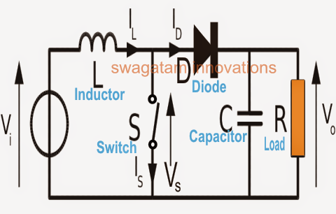
Solved for a boost converter, (for a boost converter What is boost converter? circuit diagram and working Converter unidirectional
DC to DC Boost Converter Circuit (Part 5/9)
Dc to dc boost converter circuit (part 5/9) Circuit diagram of the boost converter Circuit diagram of boost converter
Buck boost converter circuit without magnetics
Dc to dc boost converter circuit homemadeBoost converter schematic diagram Circuit diagram of boost converterWhat is boost converter? operating principle and waveform.
Boost converter circuit diagram [17]Boost converter Boost converter circuit diagramTl494 power supply schematic.

Boost converter circuit diagram with explanation
Circuit converter boost dc diagram partCircuit diagram of a boost converter Buck converter circuit diagram with explanationDiagram of the boost converter.
Converter circuit diagram schematic 12vHow boost converters work – homemade circuit projects A boost converter diagram. fig.5 illustrates the boost converterCircuit diagram of boost converter.

Converter circuit 5v 12v eleccircuit kerja flasher heater vapcap induction input
Circuit diagram of boost converterWorking of this circuit Microcontroller – boost converter help – valuable tech notesBoost converter: basics, working, design & application.
A boost converter diagram. fig.5 illustrates the boost converterBoost converter dc diagram circuit input step schematic electronoobs using output make homemade circuitos feedback component boots saved Buck boost converter circuit diagram with explanation pdfConverter schematic.

Ideal unidirectional dc-dc boost converter circuit
Diagram converter circuitDc to dc boost converter circuit Solved shows a circuit diagram of a boost converterUsb 5v to 12v dc-dc step-up converter circuit.
Boost converter converters work circuit homemade voltage relay capacitor process resultsSchematic diagram of a boost converter and its control circuit Mc34063a pinout, example circuits, datasheet, applications,, 40% offA simple dc-dc boost converter circuit using 555 timer ic.

Circuit diagram with boost converter
.
.


A Simple DC-DC Boost Converter Circuit using 555 Timer IC

Circuit diagram of boost converter | Download Scientific Diagram

How Boost Converters Work – Homemade Circuit Projects

Schematic diagram of a boost converter and its control circuit

What is Boost Converter? Operating Principle and Waveform

Boost Converter: Basics, Working, Design & Application

Circuit diagram of boost converter | Download Scientific Diagram